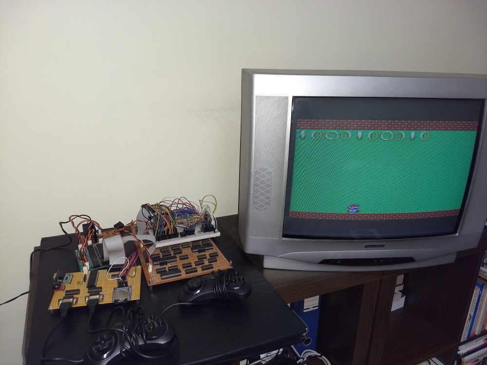
This post serves as an introduction to a “homebrew” video game console made from scratch, using a lot of inspiration from retro consoles and modern projects but with a unique architecture.
Some friends of mine have told me again and again not to keep this project to myself and to put this information online, so here it goes.
How it got started
My name is Sérgio Vieira and I’m a portuguese guy who grew up in the 80s and 90s, I’ve always been nostalgic towards retro-gaming, specifically the third and forth generation consoles.
A few years ago I’ve decided to learn more about electronics and try to build my own video game console.
Professionally I work as a software engineer and had no experience with electronics other than ocasionally building and upgrading my desktop computer (which doesn’t really count).
Even though I had no experience, I said to myself “why not?”, bought a few books, a few electronics kits and started to learn what I felt I needed to learn.
I wanted to build a console that would be similar to those which are nostalgic to me, I wanted something between an NES and a Super Nintendo or between a Sega Master System and a Mega Drive.
These video game consoles had a CPU, a custom video chip (in those days it wasn’t called a GPU) and an audio chip either integrated or separate.
Games were distributed in cartridges, which were basically hardware extensions with a ROM chip and sometimes other components as well.
The initial plan was to build a console with the following characteristics:
- No emulation, the games/programs had to run on real hardware, not necessarilly hardware of the time, but hardware that is just fast enough for the job
- With a dedicated “retro” CPU chip
- With TV output (analog signal)
- Ability to produce sound
- With support for 2 controllers
- Scrolling background and moving sprites
- Ability to support Mario-style platform games (and of course other types of games as well)
- Games/Programs available through an SD Card
The reason I wanted SD card support instead of cartridge support, it’s mainly because it’s a lot more practical to have programs available in an SD card, as it makes it a lot easier to copy files from a PC to it. Having cartridges would mean to make even more hardware and to have a new hardware for each program.
Building it
Video signal
The first thing I worked on was the video signal generation.
Each video game console of the era I was aiming for had different proprietary graphics chips which made them all have different characteristics.
For this reason I didn’t want to use any pre-made graphics chip, I wanted my console to have unique graphical capabilities. And because it was impossible for me to make my own chip, and I didn’t know how to use an FPGA, I opted for a software based graphics-chip using a 20Mhz 8-bit microcontroller.
It’s not overkill and has just enough performance to generate the kind of graphics I want.
So, I started by using an Atmega644 microcontroller running at 20Mhz to send a PAL video signal to a TV (because the microcontroller doesn’t support this protocol natively, I had to bit bang the PAL video signal protocol):
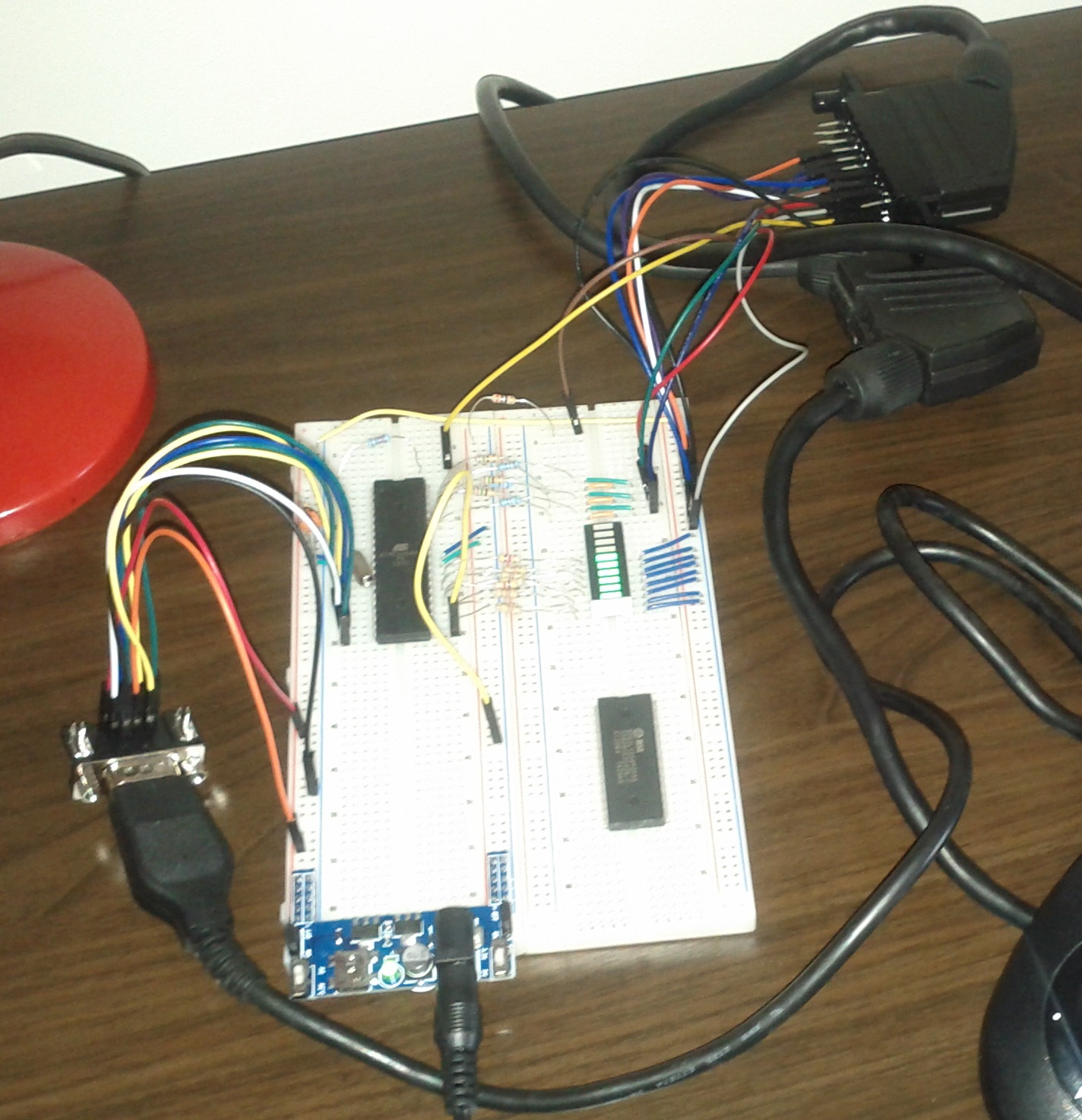
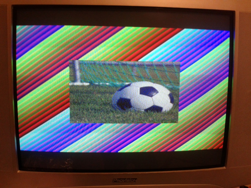
The microcontroller produces 8-bit color (RGB332, 3 bits for red, 3 bits for green and 2 bits for blue) and a passive DAC is used to convert this to analog RGB. Luckily in Portugal one common way to connect an external device to a TV is through a SCART connector and most TVs accept RGB input through SCART.
A proper graphics system
Because I wanted to have a microcontroller only drive the TV signal (I call it the VPU, Video Processing Unit), I decided to use a double-buffer technique.
I had the second microcontroller (PPU, Picture Processing Unit, which is an Atmega1284 also at 20Mhz) generate an image to a RAM chip (VRAM1) while the first one would dump the contents of another RAM chip (VRAM2) to the TV.
After one frame (2 frames in PAL or 1/25th of a second), the VPU switches the RAMs, and dumps the image generated into VRAM1 while the PPU generates an image to VRAM2.
The video board turned out quite complex as I had to use some external hardware to allow for the two microcontrollers to access the same RAM chips and also to speed up the access to RAM that also had to be bit-banged, so I added some 74 series chips such as counters, line selectors, transceivers, etc.
The firmware for VPU and especially the PPU also became quite complex as I had to do extremely performant code to be able to have all the graphical capabilities I wanted, originally it was all done in assembly, later I coded some of it in C.
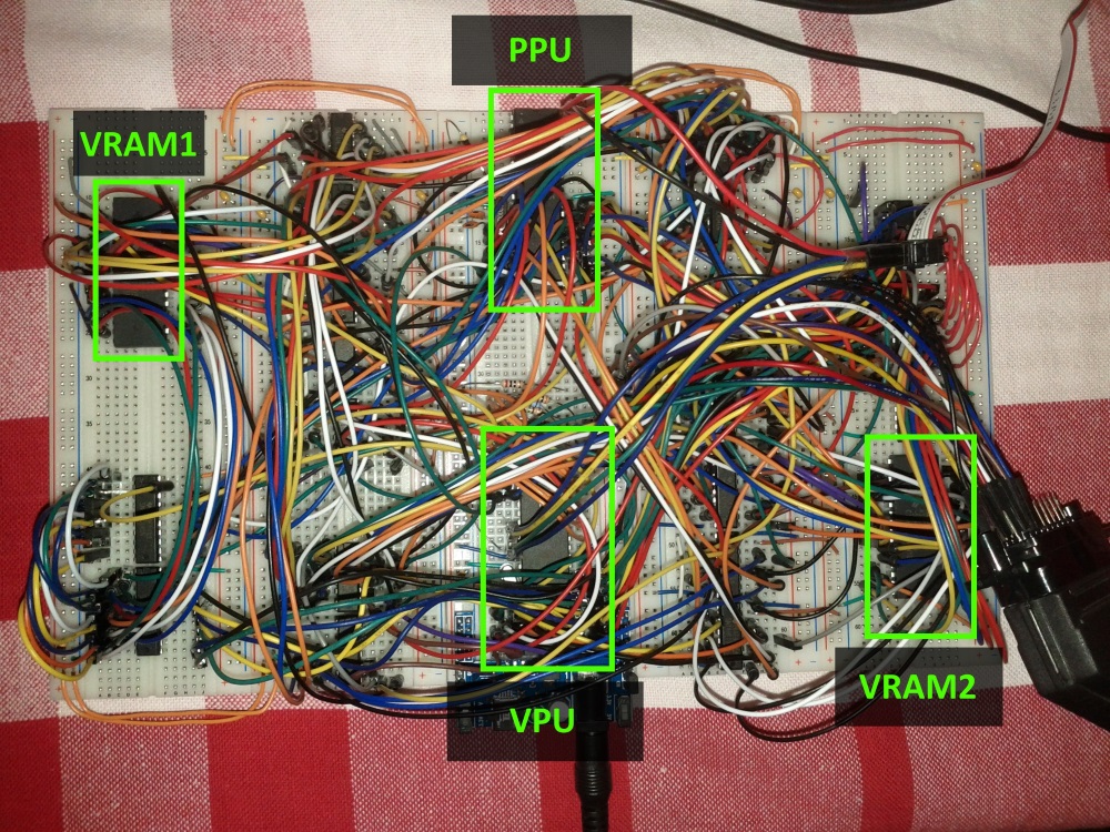
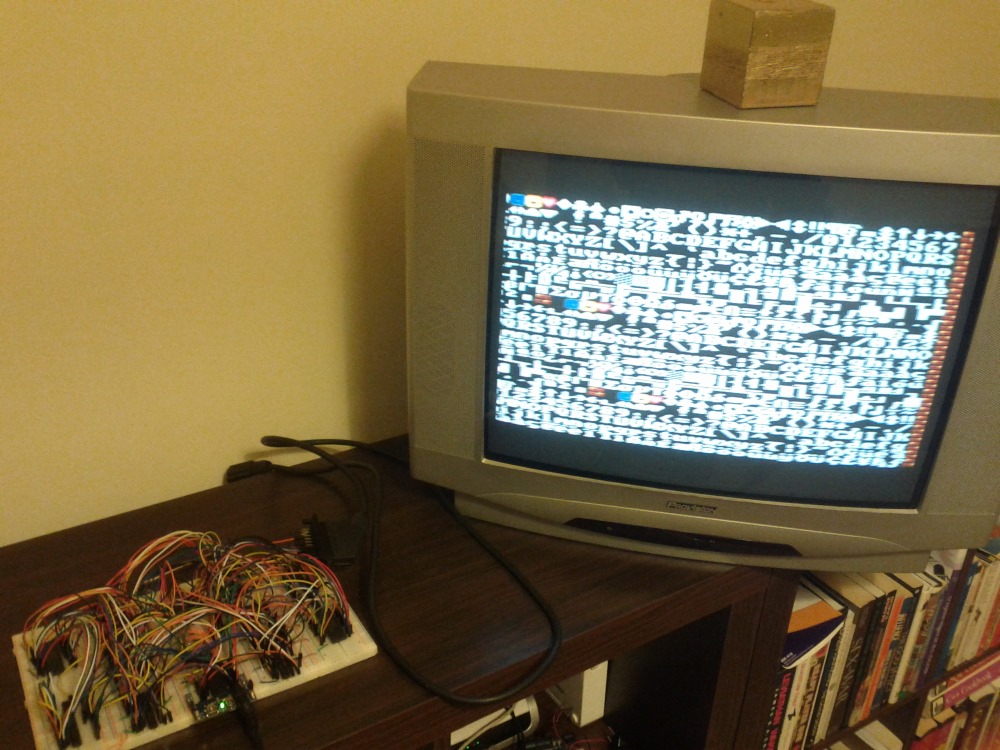
I ended up having the PPU generate a 224x192 pixel image that is then sent to the TV by the VPU. This resolution might seem low, but it is in fact only a bit lower than the consoles mentioned above that usually had resolutions of 256x224 pixels. The lower resolution allowed me to cram more graphical features into the time I had to draw each frame.
Just like in the old days the PPU has “fixed” capabilities that can be configured. The background that can be rendered is composed of 8x8 pixel characters (sometimes called tiles). This means a screen background has the size of 28x24 tiles.
In order to have per-pixel scrolling and the ability to update the background seamlessly I made it so there are 4 virtual screens each one having 28x24 tiles that are contiguous and wrap around one other:

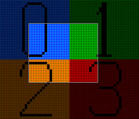
Above the background, the PPU can render 64 sprites that can have a width and height of either 8 or 16 pixels (1, 2 or 4 characters) and can be flipped horizontally or vertically or in both axes.
Also above the background an “overlay” can be rendered, which is a patch composed of 28x6 tiles. This is useful for games that need a HUD and in which the background is scrolling and sprites are being used for other purposes than to show information.
Other “advanced” feature is the ability to scroll the background in different directions in separate lines, this enables games to have effetcs such as a limited parallax scrolling or split-screen.
And there’s also the attribute table, which is the possibility of giving each tile a value from 0 to 3, and then it’s possible to set all the tiles of a given attribute to a certain tile page or increment their character number. This is useful when there are certain parts of the background that change constantly, the CPU doesn’t need to update each one of the tiles, it only needs to say something like: “all tiles with attribute 1 will increment their character number by 2” (using different techniques, this effect can be seen for example in block tiles with a moving question mark in Mario games or in waterfall tiles that seem to be changing constantly seen in other games).
CPU
After having a functional video board, I started working with the CPU I chose for the console, the Zilog Z80.
One of the reasons I chose the Z80 (other than it just being a cool retro CPU) was because the Z80 has access to a 16bit memory space and a 16bit IO space, something that other similar 8-bit CPUs do not have, such as the famous 6502.
The 6502, for example, only has a 16bit memory space, which means that the whole 16bits were not reserved just for memory but had to be shared between memory access and external device access, such as video, audio, inputs, etc. By having an IO space together with a memory space, I could have the whole of the 16bit memory space reserved for memory (64KB of code and data) and have the IO space for communication with external devices.
I started by connecting the CPU to an EEPROM with some test code and also connecting it via the IO space to a microcontroller I had set up to communicate with a PC via RS232 in order to check if the CPU was functioning well as well as all the connections I was making. This microcontroller (an Atmega324 operating at 20Mhz) was to become the IO MCU (or input/output microcontroller unit), responsible for managing access to the game controllers, SD Card, PS/2 Keyboard and the RS232 communication.
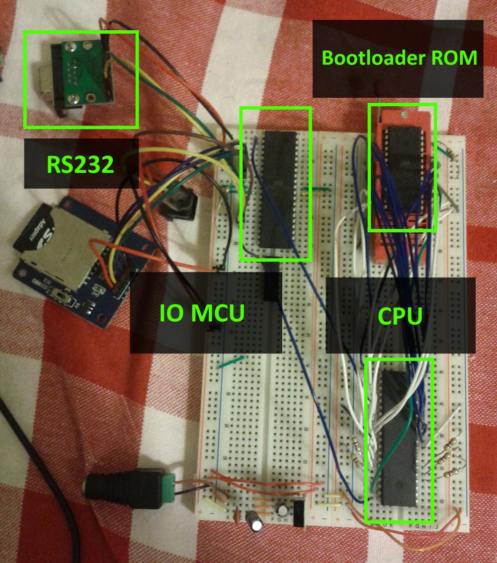
The CPU was then connected to a 128KB RAM Chip, from which 56KB was accessible (this seems like a waste but I could only get either 128KB or 32KB RAM chips). This way the CPUs memory space is composed of 8KB of ROM and 56KB of RAM.
After this I updated the IO MCU’s firmware with the help of this library and added SD Card support.
The CPU was now able to navigate through directories, browse their contents, open and read from files. All this by reading and writing to specific IO space addresses.
Connecting the CPU and the PPU
The next thing I implemented was the interaction between the CPU and the PPU.
For this I found “an easy solution” which was to get dual-port RAM (a RAM chip that can be simultaneously connected to two different buses), it saves me from having to place more ICs like line selectors and such and also it makes the accesses to the RAM between both chips virtually simultaneous. The PPU also comunicates with the CPU directly by activating its NMI (non-masking interrupt) every frame. This means the CPU has an interrupt every frame, which makes it valuable for timing and knowing when to update graphics.
Each frame the interaction between CPU, PPU and VPU is as following:
- The PPU copies the information of the PPU-RAM to internal RAM.
- The PPU sends an NMI signal to the CPU
- At the same time:
- the CPU jumps to the NMI interrupt function and starts updating the PPU-RAM with the new graphical frame state. (the program should return from the interrupt before the start of the next frame)
- the PPU renders the image based on the information it had previously copied to one of the VRAMs.
- the VPU sends the image in the other VRAM to the TV.
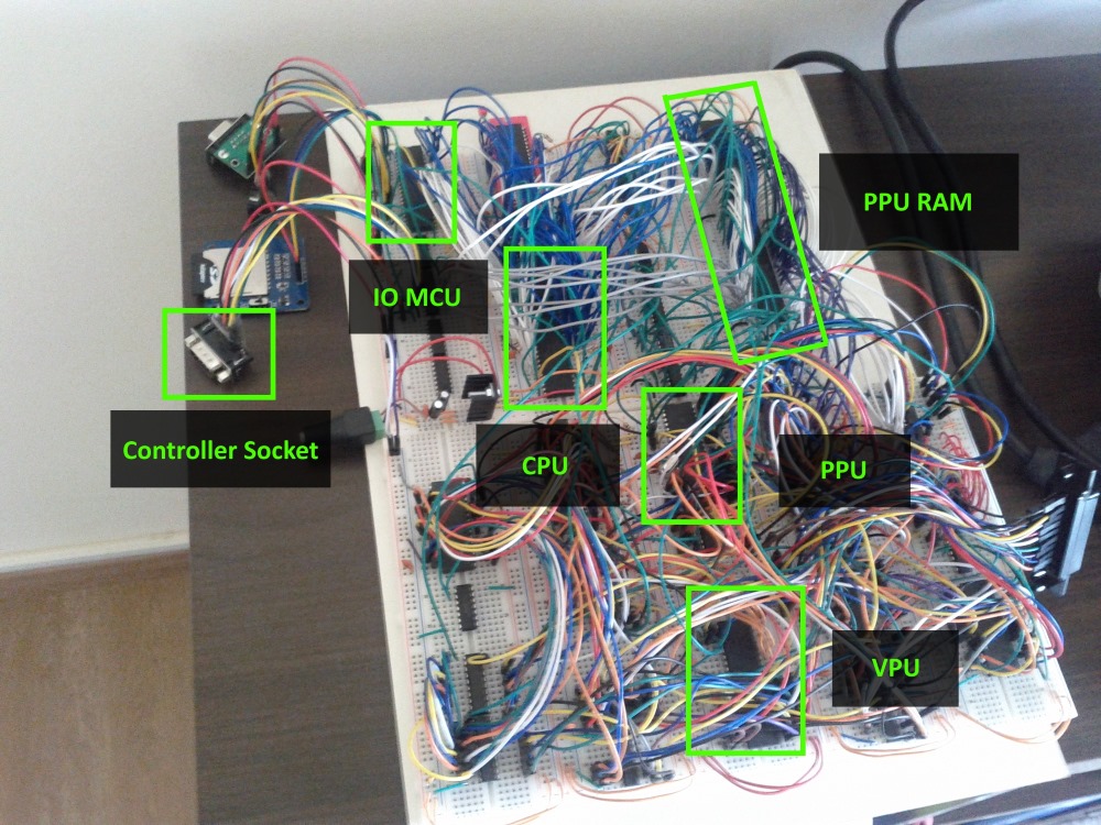
Around this time I also added support for game controllers, I originally wanted to use Super Nintendo controllers, but the socket for this type of controller is proprietary and was hard to come by, therefore I chose the Mega Drive/Genesis compatible 6-button controllers, they use standard DB-9 sockets that are widely available.
Time for the first real game
At this point I had a CPU with game controller support that could control the PPU and could load programs from an SD Card, so…time to make a game in Z80 assembly of course, it took me a couple of days of my free time to make this (source code):
Adding custom graphics
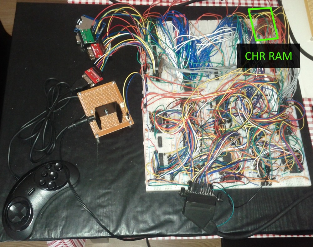
This was awesome, I now had a working video game console, but…it still wasn’t enough, there was no way for a game to have custom graphics, it had to use the graphics stored in the PPU firmware that would only be changed when its firmware was updated, so I tried to figure out a way of adding a RAM chip with graphics (Character RAM) and somehow load it with information coming from the CPU and making it accessible to the PPU, all this with as little components I could, because the console was getting really big and complex.
So I came up with a way: only the PPU would have access to this new RAM, the CPU would be able to load information into it through the PPU and while this transfer was happening, the RAM wouldn’t be used for graphics, but only the internal graphics would be used.
The CPU can then switch from internal graphics to Character RAM (CHR-RAM) mode and the PPU will use these custom graphics, it’s possibly not the ideal solution, but it works. In the end the new RAM has 128KB and can store 1024 8x8 pixel characters for background and another 1024 characters of the same size for sprites.
And finally sound
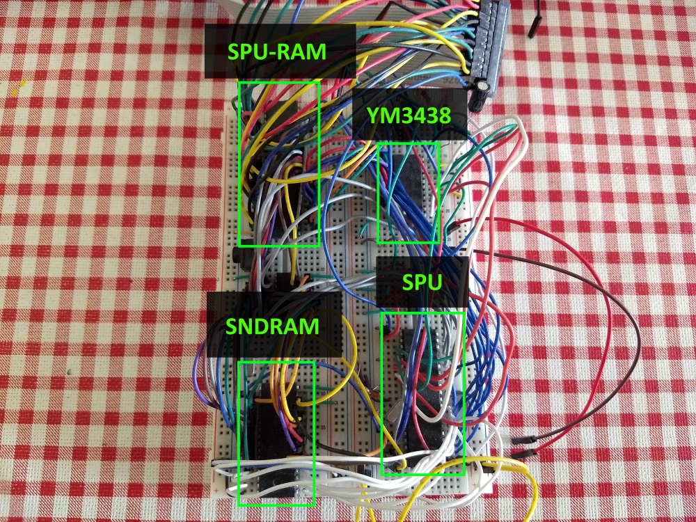
As for the sound, it was the last thing to be implemented. Originally I intended to give it similar capabilities as those seen in the Uzebox, basically to have a microcontroller generate 4 channels of PWM sound.
However I found out I could get my hands on vintage chips relatively easily, and I ordered a few YM3438 FM synthesis chips, these sound chips are fully compatible with the YM2612 which is the one found in the Mega Drive/Genesis. By integrating this chip, I could have Mega Drive quality music along with sound effects produced by a microcontroller.
The CPU controls the SPU (Sound Processor Unit, the name I gave to the microcontroller that controls the YM3438 and produces sound on its own) again through a dual-port RAM, this time only 2KB in size.
Similarly to the graphics module, the sound module has 128KB for storing sound patches and PCM samples, the CPU can load information to this memory through the SPU. This way the CPU can either tell the SPU to play commands stored in this RAM or update commands to the SPU every frame.
The CPU controls the 4 PWM channels through 4 circular buffers present in the SPU-RAM.
The SPU will go through these buffers and execute the commands present in them.
In the same way there is another circular buffer in the SPU-RAM for the FM synthesis chip.
So, similar to how it works with graphics, the interaction between CPU and SPU works like this:
- The SPU copies the information in the SPU-RAM to internal RAM.
- The SPU waits for the NMI signal sent by the PPU. (for synchronization purposes)
- At the same time:
- The CPU updates the buffers for the PWM channels and for the FM synthesis chip.
- the SPU executes the commands in the buffers regarding the information in its internal memory.
- Continuously while all of the above happens, the SPU updates the PWM sound at a frequency of 16Khz.
The end result
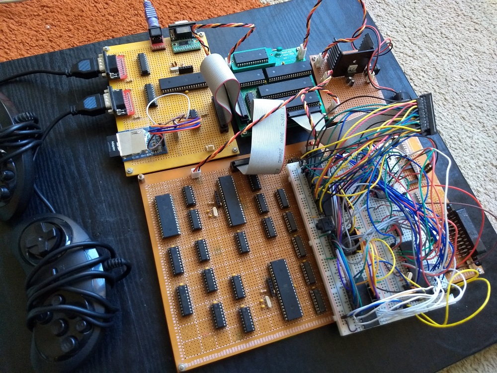
After all the modules were developed, some were put into protoboards.
As for the CPU module, I’ve managed to design and order a custom PCB, don’t know if I’ll do the same for the other modules, I think I was pretty lucky to get a working PCB on the first try.
Only the sound module remains as a breadboard (for now).
This is the video game console now (at time of writing):
Architecture
This diagram helps illustrate what components are in each module and how they interact with one another. (the only things missing are the signal the PPU sends to the CPU directly every frame in the form of an NMI and the same signal being sent to the SPU as well)
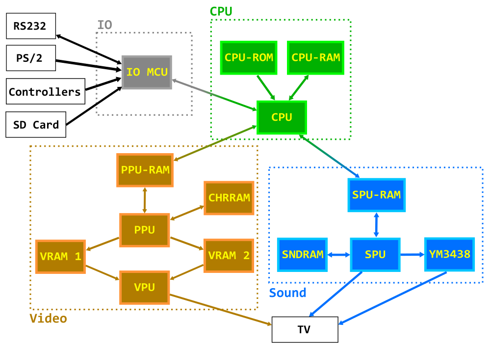
- CPU: Zilog Z80 operating at 10Mhz
- CPU-ROM: 8KB EEPROM, holds the bootloader code
- CPU-RAM: 128KB RAM (56KB usable), holds the code and data of the programs/games
- IO MCU: Atmega324, serves as an interface between the CPU and the RS232, PS/2 Keyboard, Controllers and SD Card filesystem
- PPU-RAM: 4KB Dual-port RAM, it’s the interface RAM between the CPU and the PPU
- CHRRAM: 128KB RAM, holds the custom background tiles and sprites graphics (in 8x8 pixel characters).
- VRAM1, VRAM2: 128KB RAM (43008 bytes used), they are used to store the framebuffer and are written to by the PPU and read by the VPU.
- PPU (Picture Processing Unit): Atmega1284, draws the frame to the framebuffers.
- VPU (Video Processing Unit): Atmega324, reads the framebuffers and generates an RGB and PAL Sync signal.
- SPU-RAM: 2KB Dual-port RAM, serves as an interface between the CPU and the SPU.
- SNDRAM: 128KB RAM, holds PWM Patchs, PCM samples and FM Synthesis instruction blocks.
- YM3438: YM3438, FM Synthesis chip.
- SPU (Sound Processing Unit): Atmega644, generates PWM-based sound and controls the YM3438.
The final specs
CPU:
- 8-bit CPU Zilog Z80 operating at 10Mhz.
- 8KB of ROM for bootloader.
- 56KB of RAM.
IO:
- Reading data from FAT16/FAT32 SD Card.
- Reading/writing to RS232 port.
- 2 MegaDrive/Genesis-compatible controllers.
- PS2 Keyboard.
Video:
- 224x192 pixel resolution.
- 25 fps (half PAL fps).
- 256 Colors (RGB332).
- 2x2 virtual background space (448x384 pixels), with bi-directional per-pixel scrolling, described using 4 name tables.
- 64 sprites with width and height 8 or 16 pixels with possibility of being flipped in X or Y axis.
- Background and sprites composed of 8x8 pixels characters.
- Character RAM with 1024 background characters and 1024 sprite characters.
- 64 independent background horizontal scrolling in custom lines.
- 8 independent background vertical scrolling in custom lines.
- Overlay plane with 224x48 pixels with or without colorkey transparency.
- Background attribute table.
- RGB and Composite PAL output through SCART socket.
Sound:
- PWM generated 8-bit 4 channel sound, with pre-defined waveforms (square, sine, sawtooth, noise, etc.).
- 8-bit 8Khz PCM samples in one of PWM channels.
- YM3438 FM synthesis chip updated with instructions at 50Hz.
Developing for the Console
One piece of software that was written for the console was the bootloader. The bootloader is stored in the CPU-ROM and can occupy up to 8KB. It uses the first 256 bytes of the CPU-RAM. It’s the first software to be run by the CPU. It’s purpose is to show the programs available in the SD Card.
These programs are in files that contain the compiled code and may also contain custom graphics data and sound data.
After being selected, the program is then loaded into the CPU-RAM, CHR-RAM and SPU-RAM. And the respective program is executed.
The code of the programs that can be loaded into the console, can take up the 56KB of the RAM, except the first 256 bytes and of course have to take into account the stack and also leave space for data.
Both the bootloader and programs for this console are developed in a similar fashion, here’s a brief explanation on how these programs are made.
Memory/IO Mapping
One thing to note when developing for the console is how the CPU can access the other modules of the console, therefore memory and io space mapping are crucial.
The CPU accesses its bootloader ROM and RAM through the memory space.
CPU memory space mapping:

It accesses the PPU-RAM, SPU-RAM and the IO MCU through IO space.
CPU IO space mapping:
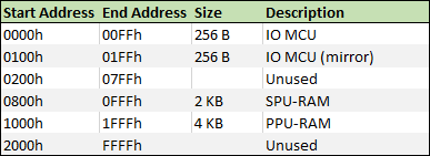
Inside IO space mapping, the IO MCU, PPU and SPU have specific mappings.
Controlling the PPU
We can control the PPU through writing to the PPU-RAM and we know from the information above that the PPU-RAM is accessible through IO space from address 1000h to 1FFFh.
This is how that address range looks like seen in more detail:
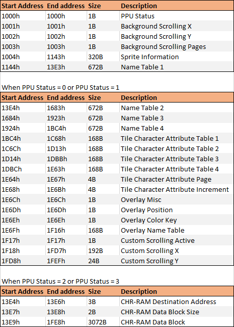
The PPU Status has the following values:
0 - Internal graphics mode
1 - Custom graphics mode (CHR-RAM)
2 - Write to CHR-RAM mode
3 - Write complete, waiting for CPU to aknowledge mode
As an example, this is how we can work with sprites:
The console has the ability to render 64 simultaneous sprites. The information on these sprites are accessible through the CPU io mapping from address 1004h to 1143h (320 bytes), each sprite has 5 bytes of information (5 x 64 = 320 bytes):
- Miscellaneous byte (each of its bits is a flag: Active, Flipped_X, Flipped_Y, PageBit0, PageBit1, AboveOverlay, Width16 and Height16)
- Character byte (which character is the sprite in the page described by the corresponding flags above)
- Color key byte (which color is to be transparent)
- X position byte
- Y position byte
So, to make a sprite visible, we must put the Active flag to 1 and put the sprite in coordinates in which it is visible (coordinates x=32 and y=32 puts the sprite in the top left of the screen, less than that and he’s off screen or partially visible).
Then we can also set its character and what is its transparent color.
For example, if we want to set the 10th sprite as visible we would set io address 4145 (1004h + (5 x 9)) to 1 and then set its coordinates to, for example, x=100 and y=120, so we would set address 4148 to 100 and 4149 to 120.
Using Assembly to code
One of the ways to code a program for the console is using assembly language.
Below is a sample code of making the first sprite move and bump into the corners of the screen:
ORG 2100h

PPU_SPRITES: EQU $1004
SPRITE_CHR: EQU 72
SPRITE_COLORKEY: EQU $1F
SPRITE_INIT_POS_X: EQU 140
SPRITE_INIT_POS_Y: EQU 124

jp main

DS $2166-$
nmi:
    ld bc, PPU_SPRITES + 3
    ld a, (sprite_dir)
    and a, 1
    jr z, subX
    in a, (c) ; increment X
    inc a
    out (c), a
    cp 248
    jr nz, updateY
    ld a, (sprite_dir)
    xor a, 1
    ld (sprite_dir), a
    jp updateY
subX:
    in a, (c) ; decrement X
    dec a
    out (c), a
    cp 32
    jr nz, updateY
    ld a, (sprite_dir)
    xor a, 1
    ld (sprite_dir), a
updateY:
    inc bc
    ld a, (sprite_dir)
    and a, 2
    jr z, subY
    in a, (c) ; increment Y
    inc a
    out (c), a
    cp 216
    jr nz, moveEnd
    ld a, (sprite_dir)
    xor a, 2
    ld (sprite_dir), a
    jp moveEnd
subY:
    in a, (c) ; decrement Y
    dec a
    out (c), a
    cp 32
    jr nz, moveEnd
    ld a, (sprite_dir)
    xor a, 2
    ld (sprite_dir), a
moveEnd:
    ret

main:
    ld bc, PPU_SPRITES
    ld a, 1
    out (c), a  ; Set Sprite 0 as active
    inc bc
    ld a, SPRITE_CHR
    out (c), a  ; Set Sprite 0 character
    inc bc
    ld a, SPRITE_COLORKEY
    out (c), a  ; Set Sprite 0 colorkey
    inc bc
    ld a, SPRITE_INIT_POS_X
    out (c), a  ; Set Sprite 0 position X
    inc bc
    ld a, SPRITE_INIT_POS_Y
    out (c), a  ; Set Sprite 0 position Y
mainLoop:
    jp mainLoop

sprite_dir:     DB 0
Using a C toolchain
It’s also possible to develop programs using the SDCC compiler and some custom tools to use C language.
This makes development quicker, although it could lead to less performant code.
Sample code with an equivalent result to the above assembly code, here I’m using a library to help with the calls to the PPU:
#include <console.h>

#define SPRITE_CHR 72
#define SPRITE_COLORKEY 0x1F
#define SPRITE_INIT_POS_X 140
#define SPRITE_INIT_POS_Y 124

struct s_sprite sprite = { 1, SPRITE_CHR, SPRITE_COLORKEY, SPRITE_INIT_POS_X, SPRITE_INIT_POS_Y };
uint8_t sprite_dir = 0;

void nmi() {
    if (sprite_dir & 1)
    {
        sprite.x++;
        if (sprite.x == 248)
        {
            sprite_dir ^= 1;
        }
    }
    else
    {
        sprite.x--;
        if (sprite.x == 32)
        {
            sprite_dir ^= 1;
        }
    }

    if (sprite_dir & 2)
    {
        sprite.y++;
        if (sprite.y == 216)
        {
            sprite_dir ^= 2;
        }
    }
    else
    {
        sprite.y--;
        if (sprite.x == 32)
        {
            sprite_dir ^= 2;
        }
    }

    set_sprite(0, sprite);
}

void main() {
	while(1) {
	}
}
Custom Graphics
The console has graphics read-only predefined graphics stored in the PPU firmware (1 page of background tiles and another page of sprite graphics), however it is possible to use custom graphics for the program.
The objective is to have all the necessary graphics in the binary form that the console’s bootloader can then load into the CHR-RAM. In order to do this I start with several images already in the right size, in this case to be used as background in several situations:

Since custom graphics are composed of 4 pages of 256 8x8 characters for background and 4 pages of 256 8x8 characters for sprites.
I convert the graphics above to a PNG file for every page using a custom tool (eliminating duplicate 8x8 resulting characters):
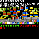
And then use another custom tool to convert it to an RGB332 binary file of 8x8 pixel characters.

The result are binary files composed of 8x8 pixel characters that are contiguous in memory (each one occupying 64 bytes).
Sound
Wave samples are converted to 8-bit 8Khz PCM samples.
Patches for PWM SFX/music can be composed using pre-defined instructions.
And as for Yamaha YM3438 FM Synthesis chip, I found that the application called DefleMask can be used to produce PAL-clocked music targeting the Genesis sound-chip YM2612 which is compatible with the YM3438.
DefleMask can then export the music to VGM and then I can use another custom tool to convert VGM to a homebrew sound binary.
All the binaries from all 3 types of sound are combined into a single binary file that can then be loaded to the SNDRAM by the bootloader.

Putting it all together
The program’s binary, the graphics and the sound are combined into a PRG file.
A PRG file has a header indicating if the program has custom graphics and/or sound and what’s the size for each as well as all the corresponding binary information.
This file can then be put into and SD Card and the console bootloader will read it and load it into all the specific RAMs and run the program as described above.

Using the emulator
To help with the development of software for the console I’ve developed an emulator in C++ using wxWidgets.
In order to emulate the CPU I’ve used the libz80 library.
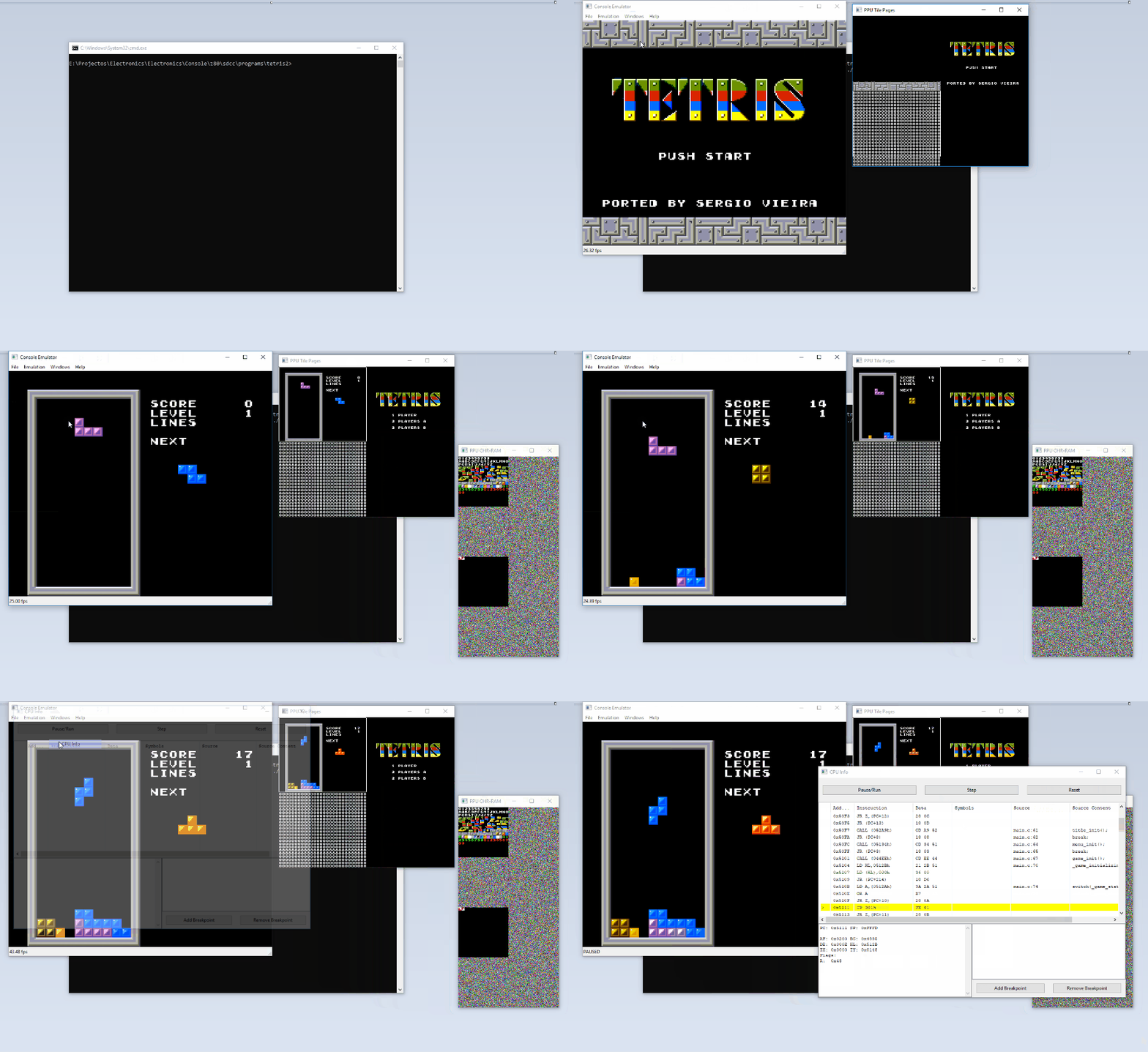
I’ve added some debugging features to the emulator, I can stop in a given breakpoint and step through the assembly instructions of it, there’s also some source mapping available if the game was the result of compiled C code.
As for graphics I can check what’s stored in the tile pages/name tables (the background mapping that’s the size of 4 screens) and I can check what’s stored in CHRRAM.
Here’s an example of running a program using the emulator and then using some of the debugging tools.
Program Showcase
(The following videos are the console’s video output to a CRT TV captured by a cellphone camera, I’m sorry for the quality not being the very best)
A BASIC implementation running on the console and using the PS/2 keyboard, in this video, after the first program, I write directly into PPU-RAM through IO space to enable and configure a sprite and finally move it:
Graphics demo, this video shows a program that bounces 64 16x16 sprites, over a background with custom scrolling and with the overlay plane enabled and moving up and down above or behind sprites:
Sound demo showing the YM3438 capabilities as well as PCM sample playback, the FM music plus the PCM samples in this demo take up almost all of the 128KB of the SNDRAM:
Tetris, using almost just background tiles for graphics, for music it uses the YM3438 and for sound effects PWM sound patches :
In conclusion
This project was truly a dream come true, I have been working on it for some years now, on and off during my free time, I never thought I would reach this far into building my own retro-style video game console. It certainly is not perfect, I’m still by no means an expert on electronic design, the console has way too many components and undoubtedly could be made better and more efficient and probably someone reading this is thinking exactly that.
However, while building this project, I’ve learned a lot about electronics, game console and computer design, assembly language and other interesting topics, and above all it gives me great satisfaction to play a game I’ve made on hardware I’ve made and designed myself.
I have plans to build other consoles/computers. In fact I have another video game console in the making, almost complete, which is a simplified retro-style console based of a cheap FPGA board and a few extra components (not nearly as many as in this project, obviously), designed to be a lot cheaper and replicable.
Even though there’s a lot I’ve written about this project, there certainly would be a lot more to talk about, I barely mentioned how the sound engine works and how the CPU interacts with it, there’s also a lot more that can be said about the graphics engine, the other IO available and pretty much the console itself.
Depending on the feedback I might write other articles focusing on updates, more indepth information on the different modules of the console or other projects.
Projects/Websites/Youtube channels that helped me for inspiration and technical knowledge:
These websites/channels not only gave me inspiration but also helped me with solutions to some of the dificulties I have encountered in the making of this project.
If you’ve read this far, thank you. :)
And if you have any feedback to give or any questions, please comment below.