Over two years after my first post on a Homebrew Video Game Console, I’m writing another one on a new Homebrew video game console.
I’m horrible on posting updates to my projects, so this is another monstrous post, showing my newest project.
As I’ve done in other posts, I’ll try to explain what made me build another console, the decision process while designing and building it as well as the final result.
Along the way I’ll try explain some concepts (or at least how I understand them) that may be simple or well known to some, but maybe it’ll helpful for others. I will also use my other homemade console as a comparison (link here). There’ll be links on topics that I feel could be worthy of further exploration by the reader.
Why another video game console
I do have a tendency to start many different projects, I’m constantly thinking of other possibilities and ways to improve and change current projects, even before I finish them. And while I was finishing the other console I was already thinking on how I could do better or at least do different.
I really like my first video game console, but is has a few drawbacks:
- Updates the screen at 25 frames per second
- Has a one frame delay between updating and rendering
- No color palettes
- Resolution of 224x192 (a bit less than I was hoping for)
- It’s a really complex design with a lot of different components
Added to this, a friend of mine told me: “hey, I would really like to own one of those”, and being so complex and huge made it very hard and expensive to replicate.
So, I set off to make a video game console which improves in some aspects, but it’s not necessarily an evolution over the first one.
Must-haves
Having this in mind, I had some must-haves for the new console, some new and some I brought over from the previous project:
- For the game logic there must be an 8-bit CPU
- It must have sound
- Graphics
- Resolution of 256x224 pixels, a more standard resolution when comparing to other retro systems
- Tiled background
- Multiple sprites on top of the background
- Possibility of using palettes for the background and sprites
- Ability to change some graphical configurations mid-frame
- 50 fps (PAL frequency) with no frame delays
- It must be able to load programs through an SD Card
- Have support for two game controllers
- There must be few components and a small form factor
- Is cheaper to make and easier to put together than the first one
- There must be no software emulation and there must be no components too powerful that they would need to be extremely underused or slowed down to keep it retro-styled
Choosing the Hardware
After this I started to research what components I could use so that I ended up with the fewest possible but enough to make everything work, of course. And a constant in these kinds of projects, nothing too overkill, no software emulation, no mini-pc boards, nothing like that.
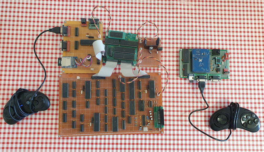
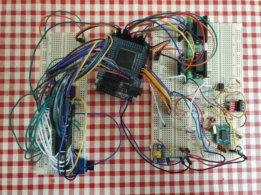 (the console when in breadboards)
FGPA
This project gave me the opportunity to work with a kind of component I’ve always wanted to work with: FPGAs (Field Programmable Gate Array). FPGAs are versatile components that can be configured to behave as different circuits. Most video game consoles back in the day had specific chips for things like video and sound and for most hobbyists building their own ASICs is simply not an option, so using FPGAs are a great alternative to this. Besides, all “the cool kids” are using it and I wanted to use it as well.
In my last console I’ve used something similar, a PLD (Programmable Logic Device) to help with some of the glue logic and save on 7400 series ICs that needed to be used.
FPGAs however have some differences in comparison to PLDs or CPLDs, in most cases:
- they don’t support 5V logic (most retro systems from the 80s and early 90s are 5V)
- their configuration is saved in an external component and loaded into the FPGA when powered on (there’s a slight delay when turned on)
- they generally support greater speeds and more complex circuits configured
- they have internal RAM usable by the configured circuits
Creating a design for an FPGA usually means using a high level design language such as VHDL or Verilog (there are others as well) and defining each component, inputs, outputs, behavior, etc.
An FPGA would enabled me to save on the number of components used as I could design many of them inside of it. I didn’t want however an FPGA that was way too powerful for what I was trying to accomplish (again, a personal rule for my “retro” projects: I can use current technology, but I have to make sure it’s not overpowered).
I also knew that I was not going to be able to design a board that would use an FPGA directly as I lack the experience in electronic circuit design to do it, so I had to pick a pre-made FPGA development board to use in the console, something cheap with an FPGA just powerful enough for the project, with a lot of available pins and no extra hardware or connectors (common in FPGA development boards).
I found just the board:
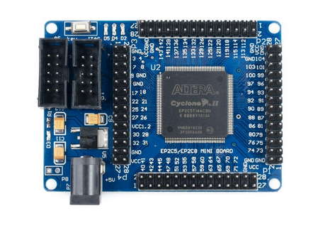
It retails for $12 to $15 and it can be found in several vendors such as AliExpress and Ebay at the time of writing, it has 143 Input/Output pins (not all of them available) and holds an Intel (formerly Altera) Cyclone II EP2C5 FPGA. (right now there are cheaper boards with more recent FGPAs, however when I bought it a few years ago it seemed to be the best and cheapest option)
The Cyclone II series of FPGAs is a now discontinued series although it is still widely available.
This model in particular has:
- 119.808 bits of internal RAM (known as Block RAM)
- 4.608 logic elements
The number of logic elements determines the complexity of the circuit that an FPGA can hold and 4608 is enough for a lot of the console but not amazing, FGPAs can easily have many more logic elements available.
It is not easy to know how many logic elements are needed for a certain circuit design until you’ve actually designed it, it’s hard to predict how a circuit is converted into an FPGA configuration, furthermore depending on the FGPA vendor, logic elements can have different meanings (they can be more or less complex) and even slightly different names making it harder to compare them.
The block RAM was going to be extremely useful, I knew I wanted the FGPA to at least do the video and graphics, and the interface between the CPU and graphics circuit was going to be RAM like in the previous console. And the block RAM can easily be configured as dual-port SRAM, which is a great way to interface two components.
Ultimately the circuit design I ended up with holds:
- a Z80 CPU soft-core (I used a pre-made core, the T80)
- a YM2149/AY-3-8910 audio chip soft-core (I used a pre-made core by MikeJ from January 2005 originallly used in an FPGA version of Bomb Jack)
- a custom video and graphics circuit (that I named the named Video Signal Processor and Video Display Processor)
- a custom Sega Genesis-compatible controller reader circuit
- custom glue logic
Like I mentioned above, FPGA design is usually done in a high level design language, usually VHDL or Verilog, I chose VHDL for no particular reason, simply because I found more examples on it and found some pre-made cores in that language that I could use.
For the development of the FPGA design, as mentioned above, I used 2 cores made by someone else, the core for the Z80 CPU and for the sound (YM2149), the rest was designed by me, including the graphics and video processing.
I’m still not very confident in my ability with VHDL, but it is improving. It’s easy to mistakenly start using a design language as a regular programming language, but they’re two very different things with different concepts, also it’s very hard to debug these designs as opposed to regular software, so the design went through several iterations until I was confident enough that it would consistently work in all situations.
Extra Memory
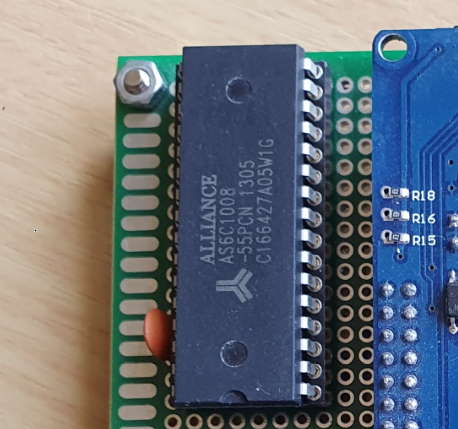
Having 119.808 bits or 14.976 bytes of RAM in the FPGA is great but not really enough to store all the data, code and graphics for a program to run in the console. So I added my trusty AS6C1008 memory IC, it has 128KB of SRAM at 55ns and it can work with either 3.3V or 5V voltage levels. This means I could interface it directly with the FPGA board as it interfaces with 3.3V but not 5V.
The usage of the memory available in this IC is split into two. The first 64KB is accessed exclusively by the CPU and it serves to store the code and data for the programs. The second 64KB is what I call the Character RAM (CHRRAM) and it stores graphics, this is accessed by the CPU through the IO port and by the VDP to render frames.
SD card reader
As one of the requirements is the ability to load programs from an SD Card, I needed a way to read them. I could design a circuit in the FGPA for this, but the FPGA ended up pretty much full without this, so I felt I could sneak in my also trusty Atmega microcontroller to do the trick and save on the FGPA “real estate” (the number of logic elements used).
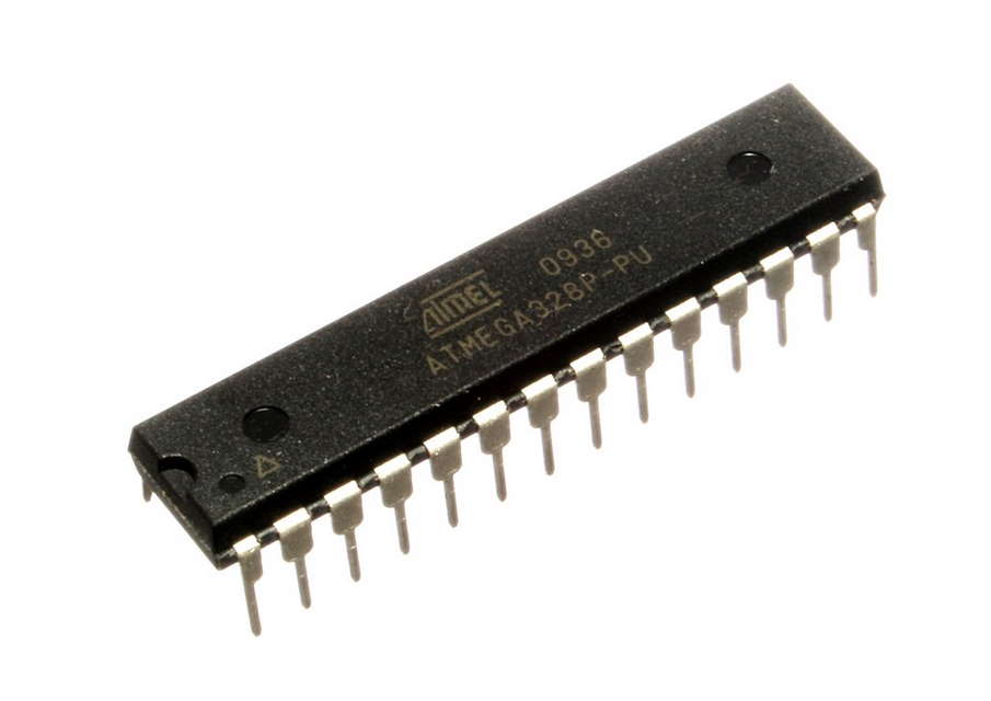
Originally I used an Atmega324 just like in the previous console and also reused most of the code to access the SD Card. Although I thought I could do a little better, so I ended up swapping it for an Atmega328, the same used in the Arduino Uno. This one has less pins (it’s smaller) and it’s a lot cheaper. The only drawback is that with the lack of pins, I would only be able to interface with the CPU with an address bus of 6 bits instead of the 8 bits I used in the other console. That meant I had only 64 read and 64 write instructions available, but, it was actually more than enough.
Video encoding
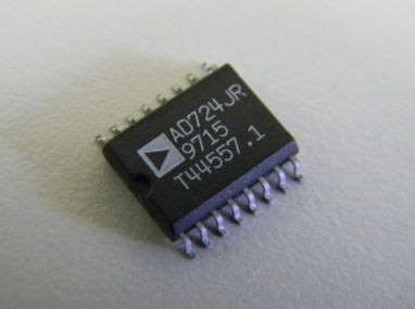
For video, to minimize the space used in the board I opted for composite video output only, instead of RGB video out. This way it would only need a small video output connector. To do this I needed a video encoder to generate the composite video signal. In the previous console I had used a vintage chip for this which is no longer manufactured, a Sony CXA1645 (???). This time I went for a modern IC, an AD724. It’s package is not very hobbyist friendly, but I managed to solder it to an adapter board and use it just fine.
The FPGA produces 8-bit RGB color signals and a Sync signal and the AD724 converts this to a composite signal.
Audio amplification
And for audio I used an LM358 as an audio amplifier, I believe it’s not the best IC for this, but it does the job. This IC amplifies the audio signal output by the FPGA.
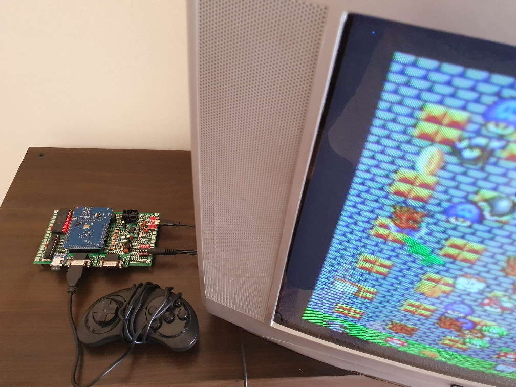
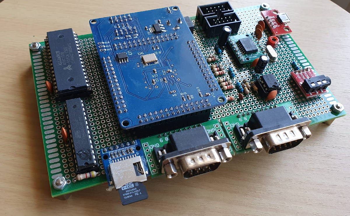
Final look
This is the console’s final look, the FPGA’s development board is plugged into the console’s board.
Console design and architecture
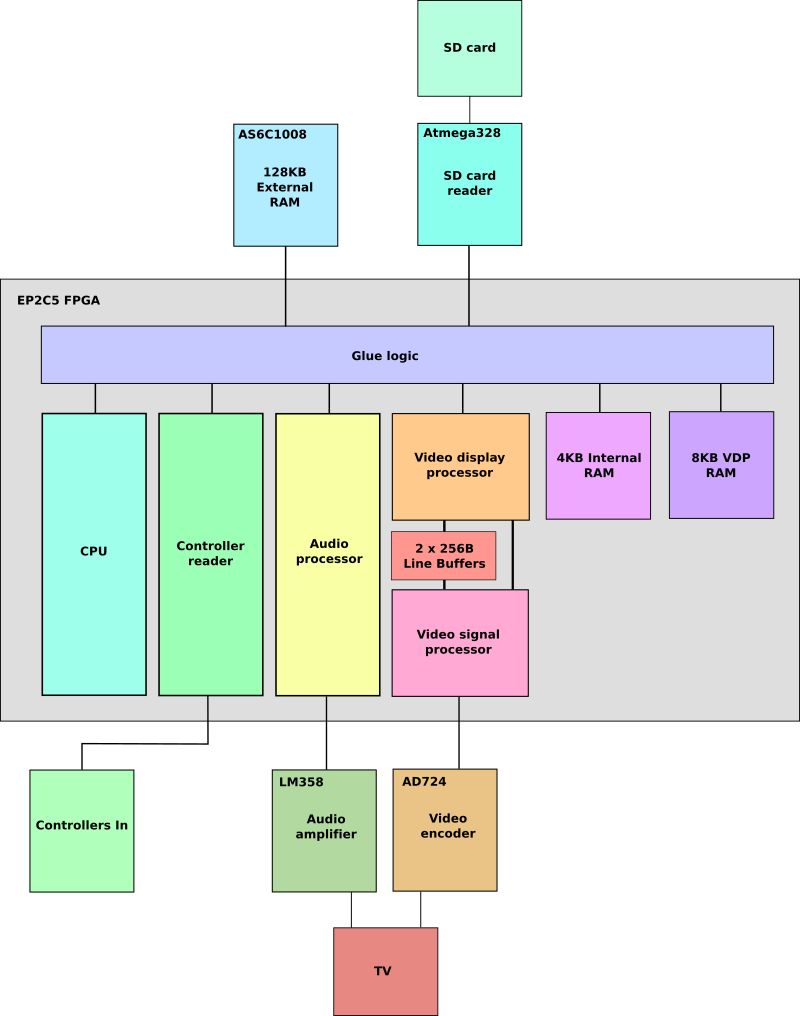
General Architecture
Here are all the components, physical and in the FPGA design:
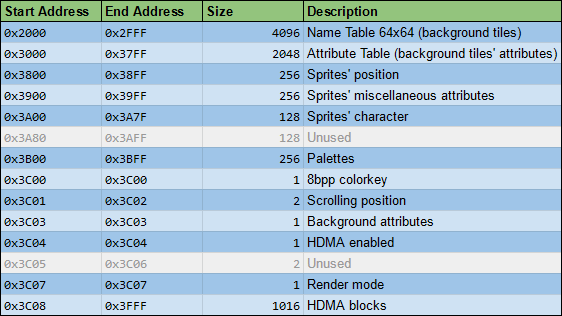
CPU and RAM and IO mapping
The soft-core CPU in the FPGA is a Z80 compatible CPU running at 16.66Mhz. As explained in previous posts one of the Z80’s advantages is that it has a 16-bit memory space as well as a 16-bit IO space. Althought they can’t be used in parallel, it enables me to use the full 16-bit of memory for the program and leave acessing other components to the IO space.
Memory space
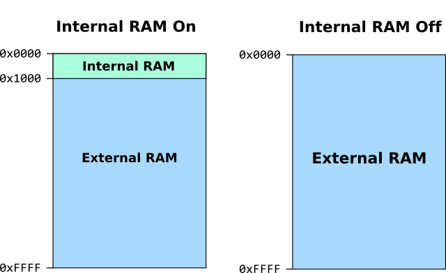
The code that is first executed when the console is turned on is located in 4KB of RAM inside in the FPGA.
The CPU has access to a full 64KB of RAM, the first 4KB of RAM can be switched between the first 4KB of the 128KB RAM chip and 4KB of RAM (Block RAM) in the FPGA.
A special address IO space can be used to switch between the internal 4KB RAM and external RAM.
IO space
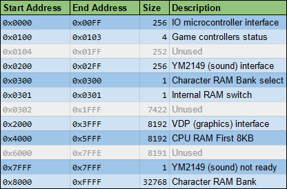
Through the IO space it’s possible to:
- Communicate with the IO IC (Atmega328) which is used to access data from the SD Card
- Read and write to the VDP RAM which defines the scene to be rendered
- Send commands to the YM2149/AY-3-8910 soft-core (audio processor)
- Switch the first 4KB of RAM from internal to external RAM
- Read game controller status
- Read and write to Character RAM in two 32KB banks
Video and Graphics
Video
For the video I went for what I’m already used to, a 50Hz PAL analog video signal, since it’s the standard here in Portugal. The resolution is 256x224 and each pixel has one of 256 colors in the color space RGB 332, the same as in the previous console.
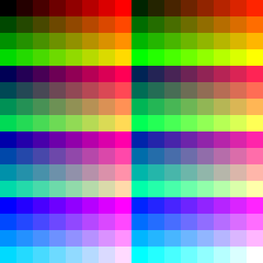 (available colors)
Graphics
The graphics are located in the Character RAM, which is 64KB of the external RAM.
They are arranged (like with the last console) in 8x8 pixel tiles each in 64 consecutive bytes.
Originally I wanted to only have 4bpp graphics (4 bits per pixel or 16 colors per pixel) and use color palettes to map each of the 16 colors to the final color in RGB332 space. However I found that not using palettes is much easier and palettes are not always necessary.
For this reason I made it possible to choose between using 4bpp with color palettes or 8bpp graphics, both for the background plane and sprites, making the VDP more complex as a consequence, but it works.
This way the number of characteres/tiles available in the 64KB of CHRRAM depends on the use of 4bpp or 8bpp graphics. It can hold up to 1024 8bpp characters or up to 2048 4bpp characters or a combination of both.
Video Display Processor (VDP)
The VDP is capable of combining a background with multiple sprites.
As in the first console and like in many retro consoles of the 80s and early 90s, the background is a virtual screen composed of 8x8 pixel tiles. The virtual screen has 64x64 tiles (in a total of 512x512 pixels) and can be scrolled horizontally and vertically.
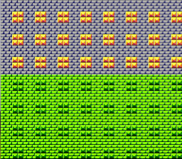
The background can also be 8bpp or 4bpp, if it’s 4bpp (16 colors) than it will use any of the available 16 palettes for the colors. It’s possible to use 4 different palettes in the same background at a time, each tile can only use one at a time.
The VDP can render 128 sprites, each one 8x8 or 16x16 pixels in size, they can also be flipped horizontally and/or vertically. Each sprite can also be 8bpp or 4bpp in color. And in case of the latter, one of the 16 palettes can be set for each sprite.
![]()
One of the things I wanted this console to have was a second background layer that could sit behind or above sprites, I had to let this go as I was having problems including this in the FPGA because of the amount of logic elements I had available and also because of timing, every horizontal line in a frame has to be rendered in 64 microseconds, the time it takes for the TV to show a horizontal line in PAL.
Because I couldn’t do this, I managed to add another feature. If the background is in 4bpp mode, then it’s possible to set each sprite above or behind the 8 last colors of the palette of the background. It’s not the same but it’s a nice addition and can do the trick for the most part.
In this example, the background is using this palette:

And so each individual sprite can be controlled to be “hidden behind” the pixels using any of the last 8 colors of the palette (index >= 7):
![]()
Every horizontal line of the frame is rendered independently and the VDP reads the scene configuration from the VDP RAM to know what to render:
HDMA
Another feature of the VDP is HDMA (H-Blank Direct Memory Access, I chose this name because the Super Nintendo had a similar feature). DMA (Direct Memory Access) are usually systems that allow access to memory without the CPU’s assistance or interference. In video game consoles they’re usually used to transfer data blocks from the several types of memory (main memory, graphics memory, sound memory, etc) faster than doing it by software, this can happen at the end of a frame or, for example, after rendering to the screen a certain horizontal line of the frame.
In this case I wanted to change the VDP RAM after rendering a horizontal line which could be used for some cool tricks, such has changing the palette of colors (underwater effects, etc), changing the scrolling values (split-screen, parallax effects, etc) and others. So in the VDP RAM there is a section for HDMA, in which you can configure a set of blocks of bytes to be copied to somewhere else in the VDP RAM after a given horizontal line.
 (In this example the HDMA is changing the palette colors at the end of a frame’s horizontal line, that line is then being changed every frame by the program)
Drawing and Rendering
For the Video Display Processor and the Video Signal Processor to work simultaneously I used a line-buffer as opposed to a frame-buffer as in the last console. With this technique I can have both systems work together and there won’t be a 1 frame delay between drawing and showing the frame.
This technique was used, for example, in the Neo Geo system.
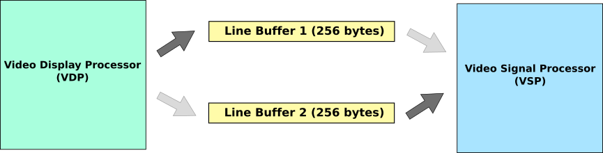
Each frame has 256x224 pixels, so each horizontal line has 256 pixels and since in the end, with or without palettes, the color resolution is always 8bpp (8 bits per pixel or 256 colors), I needed two 256 byte buffers.
So, for every horizontal line being rendered, while the VDP is rendering a line to one of the buffers, the VSP is dumping the contents of the other buffer to the line that’s is currently being displayed on the TV. Then they swtich buffers.
As mentioned above, The graphics processor needs to render an entire line of a frame in the time it takes a line to be sent to the TV, which in PAL is 64 microseconds.
This is because sending information to the TV needs to have accurate timing and cannot be stopped.
Sharing Graphics RAM between VDP and CPU
Unlike in my previous console, the CPU and Graphics processor use the same RAM IC simultaneously and it’s not a dual-port RAM IC, so access to it needs to be managed as only one component can use it at a time.
The easiest way to do this was to disable the CPU when the RAM is being used by the Video Display Processor, which is not always active.
Every frame in progressive PAL has 312 lines, not all of them are visible. The VDP is only active when rendering the visible lines.
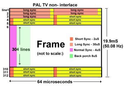
The VDP renders each frame in 224 of these lines, in which it needs to access the RAM IC, so when the VSP is sending to the TV the line before, a BUS request is sent to the CPU for it to halt and surrender access to the memory bus. When the 224 lines are rendered, the request ends and the CPU can resume work.
So the CPU only works about 27.8% (87 out of the 312 lines) of the time. Which may not seem like much, but it’s enough.
This strategy of halting the CPU while the graphics processor is using the same RAM IC was used in other systems before, like the ZX Spectrum, for example.
In my previous project, the CPU didn’t have direct access to the Character RAM and had to use the graphics component as an intermediary to move information into this RAM.
As a result, it took a couple of frames to make a simple change to the Character RAM and the graphics component couldn’t render them while being used to transfer information, so the graphics had all to be loaded before being used.
In this console the CPU can actually change the graphics in run-time, although it can’t move much data because of its processing power and only running 27.8% of the time.
Still I managed to code a simple paint program, which you can see in the video posted below, that shows this feature, now not only background tiles and sprites can be moved but also graphical character can be changed every frame.
Writing Software
Programs / Games
Developing programs for this console is very similar to the last one, even though software is not compatible between them as the graphical and sound capabilities are different and the IO memory mapping is different as well.
Once again the choice can be made between assembly language and C. C provides more productivity, so apart from early testing programs, all the software was written in this language.
For the C programs I reused the same toolchain I already had since the CPU is the same and the way graphics are stored is very similar as well.
For the C programs I still use the SDCC compiler. The only quirk about this compiler is that it expects code to be in a ROM and data to be in a separate RAM. This means that in some cases such as initialized global variables it creates unecessary code. The console runs all its code in RAM. So to go around compile all my C files to assembly than run a custom python script to rearrange the assembly code a bit and only then I compile the resulting code together to form the final binary.
Just like in the previous console, in C, like the former console, I changed the crt0 of the programs so that two functions are required:
- main: where the start code
- nmi: code that gets executed everyframe, Z80 NMI interrupt
One difference from the first console is that this one doesn’t have any predefined graphics (Character ROM, like I called it), so you always need to provide some graphics with the program or write them dinamically to the Character RAM.
 (example of the toolchain process to produce a file that can be placed in the SD Card to be read by the console’s program loader, the binary for the program is produced and combined with the graphics binaries to produce the file that is put into the SD Card)
Bootloader
The bootloader is the program that is first executed when the console is turned on.
This program is located in the internal RAM in the FPGA as the console boots up. It takes up a maximum to 4KB of RAM.
The bootloader loads a program from the SD Card into memory, it loads the program in file “program.pr2”.
It uses a function to load a specific program from a file in the SD card (in the PR2 format) and load it into the SRAM chip, the first 64KB for the code/data and the second 64KB for the graphics.
This function can be accessed by any program as it sits in a specific address of the internal 4KB RAM.
For a program to use this it must switch to internal 4KB RAM use and jump to the specific location in the code.
This means that any program can load another program into memory and use the full 64KB of RAM for code and data.
The Bootloader was developed in C but it has a custom crt0 to expose the function described above in a specific address.
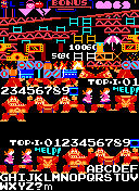
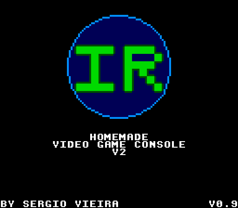
Just out of curiosity, the logo in the bootloader (you can see it in the image above) has 14x14 tiles and 5 colors and in order to fit into the 4KB together with the other code, it had to be stored as half its size and using RLE in 666 bytes and it’s decoded on runtime. I decided to make the decoding visible as it serves as a cool effect.
PR2
A new console means a new file format for programs to be stored in. In the previous one I had the PRG file format, and this one naturally uses the PR2 file format.
This is structure of the file:
- “PRG”,2,0
- Program Name (24 bytes)
- Author (24 bytes)
- Icon (256 bytes, 4 8x8 pixel tiles 8bpp)
- Program size (2 bytes)
- Characters size (2 bytes)
- Program
- Characters
The changes to the format are the introduction of metadata: the name of the program, name of the author and a 16x16 pixel icon.
Also this console doesn’t have RAM specifically for sound, so that section is not needed in this file format.
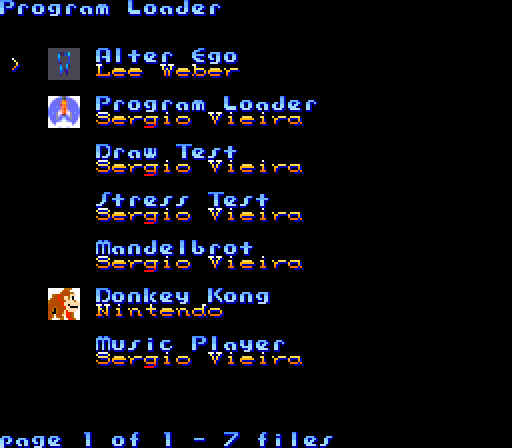
Program Loader
I decided to make the first program that is loaded by the bootloader the Program Loader.
This program shows a list of programs stored in the SD Card in the PR2 format and uses the new meta information in the those files as well.
The user can then choose a particular program that is loaded into the console’s memories.
I decided to write this as a regular program and not as the bootloader itself so that I can easily update it by dropping a new version into the sd card when needed.
This program uses the bootloader function to load programs into memory mentioned above.
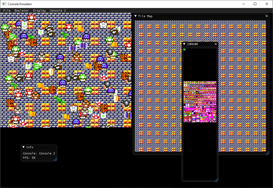
Emulator
Just like I did for the previous console I decided early on to create an emulator to make it easier to develop for this console. Originally it was a separate and standalone emulator, but later I decided to rebuild it merging the emulators for both consoles into a single one.
The emulator was done in C++, using the SDL and imGUI libraries.
Porting games from other systems
Because this console has a larger video resolution (256x224), it’s more viable to port games from other systems, particularly from the Uzebox project even though in terms of processing this console is slower that the Uzebox.
No need to change the game logic or graphics, just to code a layer replacing the Uzebox “system calls” to convert them to this console’s graphics, controller, sd card and audio management.
The sound needed some extra work as the sound chip on this console is less powerful and I made a convertion tool with less than perfect results most of the times, but it worked for the most part.
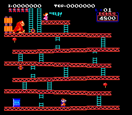
Donkey Kong ported to this console
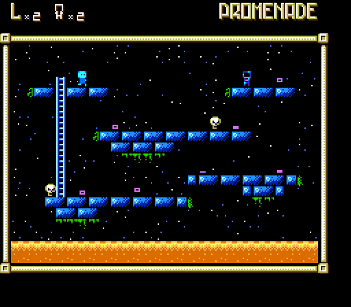
and Alter Ego
Final result
I ended up with a compact custom video game console.
Even though the software is not compatible with the previous console developing for it is quite similar.
 (The newer console next to my last project)
Final Specs:
- Z80 compatible CPU running at 16.66MHZ , running about 27% of the time.
- 64KB RAM for CPU memory space
- AY-3-8910 compatible sound
- 50fps, 256x224 pixel resolution
- 256 colors, colorspace RGB332
- 1 scrollable background layer of 64x64 tiles of 8x8 pixels each, 4bpp or 8bpp
- 128 simultaneous sprites on screen 4bpp or 8bpp, 8x8 or 16x16 pixels, with a maximum of 256 sprite pixels per line
- 16 palettes for 4bpp graphics
- 64KB RAM for graphics (Character RAM)
- HDMA that can copy up to 16 bytes per line to a location in VDP RAM
- SD Card reader
- Access to 2 Mega Drive / Genesis compatible controllers
- Composite PAL video output
Active Components:
- Atmega324p microcontroller
- AS6C1008 128KB RAM
- AD724 Video encoder
- EP2C5 FGPA development board
- LM358 op-amp
Connectors:
- 2 DB9 male connectors for the game controllers
- 3.5mm jack female to output video and audio
- micro sd card slot
- micro usb connector for power
Program Showcase
The showcase video features:
- Donkey Kong port: A port of Donkey Kong, the game was ported from the Uzebox version.
- Alter Ego port: A port of the game Alter Ego from the Uzebox by Lee Weber.
- Sprite Test program: A program that shows the 128 sprites moving on top of a background with HDMA producing a palette change effect in the background.
- Paint program: A program that changes the CHRRAM in runtime, something that couldn’t be achieved in my previous console.
- Music Player: A music player program I’ve developed to play AY-3-8910 music.
In conclusion
In a time when you can get cheap and powerful laptops and mini-PCs and other boards such as raspberry PIs where you can have complex games running on them natively or emulate tons of retro systems, why would anyone want to keep building custom underpowered retro-style game consoles?
Well actually I don’t really know the answer to that, although I do ask myself that question from time to time. All I can say is that it’s fun for me.
I enjoy building the whole thing from scratch and then getting to play with homemade software running on homemade hardware, there’s a sense of accomplishment in that. And even though everything is retro and somewhat outdated, I feel there’s still a lot of valuable knowledge to be gained from projects like this.
I haven’t posted the source code and schematics for this project or the last one yet and the reason is because I feel the quality might not be the best, things are developed to a point where they “work” but there’s a lot of room for optimization and making things more presentable. Something I never found the time to do, between my daytime job and other things in my life.
I do hope, though, that someone finds this interesting and useful and even if no one pursues a similar project, I hope it encourages and motivates someone to build their own “ambitious” projects.
I still have one last video game console I would like to build, a 16-bit CPU based console with better sound and graphics, I do have most of the components I need, I’m just not sure I’ll ever get around to do it, but we’ll see.
If you have any questions or comments, you can comment below or reach me on Twitter.
And of course, if you got this far, thank you for reading this post.